Milestone 3.2
3.2: Test
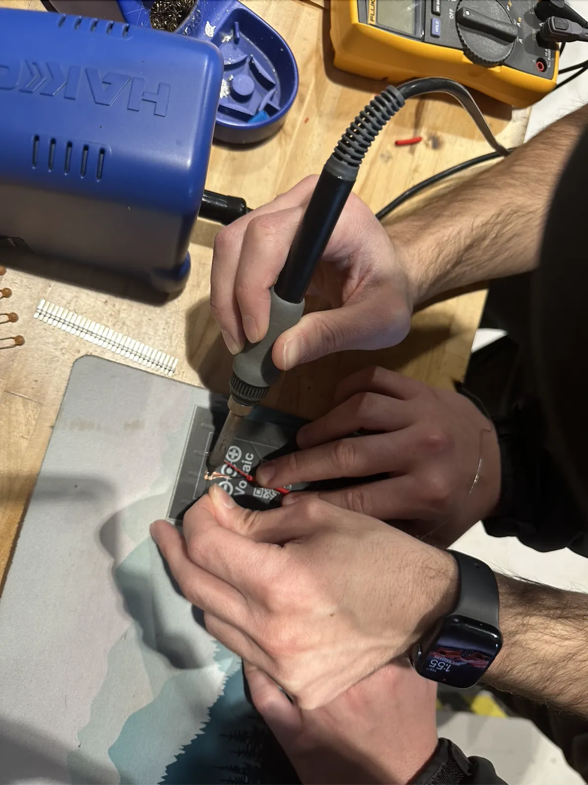
Each subsystem of the project was tested separately to ensure it would be easy to troubleshoot in the event of any errors. Where applicable, each individual part was also tested to reduce the chance of unknown defective parts or parts that weren't very compatible with each other.
Charge Testing:
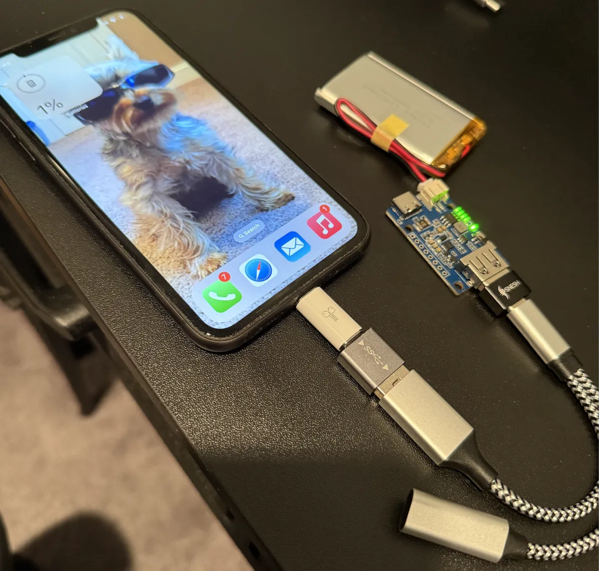
The above design successfully charged the battery. However, too much movement caused charging to stop, requiring the phone to be unplugged and plugged back in. This isn't ideal for a portable phone case that will be experiencing a lot of movement. We believed this was due to too many adaptors, so we reduced it in the next design
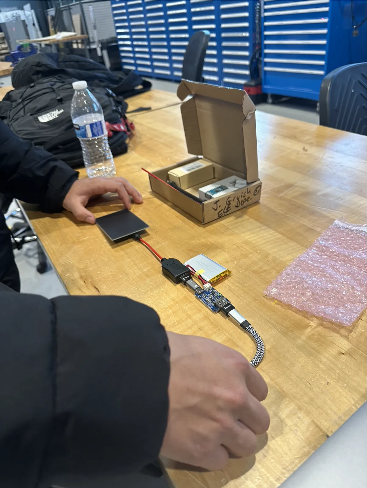
The design above reduced the number of adaptors and allowed for uninterrupted charging when motion was involved. The flexibility of the cord also makes it easier to insert into the case, however there is more wiring in this design so it may require the case to be larger.
For efficiency testing, a spare 3.7 V 2000 mAh battery was run down from approximately 80% to 0%, and charged an iPhone 11 from 1% to 30%. This results in an efficiency of 60%, excluding battery efficiency for when the new battery arrives, and also excluding battery health. However, it should also be noted that the chip indicated the battery still had between 1% and 25%, appearing to be around 10-20% from monitoring, when charging stopped.
Solar Testing:
When testing the solar panel in the Stevens maker space, we used the provided multimeter to measure the voltage at the solar panel under multiple lighting conditions.
Under the lighting conditions in the maker space, we measured about 1.3 volts, which we felt wasn't bad considering how high the light was and the fact we had a small portion of the solar panel covered to hold while testing.
The solar panel was then tested using a flashlight to increase the light intensity on the solar panel. After doing this, we measured about 3.7 volts. However, this was still not enough to charge the battery, as the voltage regulator we are currently using requires a minimum of 4.2 volts to output a steady 5 volts to the usb input of the charge controller.
The final test was using natural light. Since the multimeter wasn't allowed outside the maker space, a numerical value for the voltage wasn't recorded, but considering the chip indicated that the battery was being charged when the solar panel was placed in direct sunlight and the fact that the solar panel is a 6 volt solar panel, we can assume that the output was 6 volts.
After these tests, we concluded that the current charge system does work, but can be improved in future iterations. After research, we found we may be able to use a buck boost converter to allow a wider range of input voltage, allowing the solar panel to still work in even less than ideal conditions, improving efficiency, as even the indoor lighting would still provide approximately 20% peak power.
Display Testing:
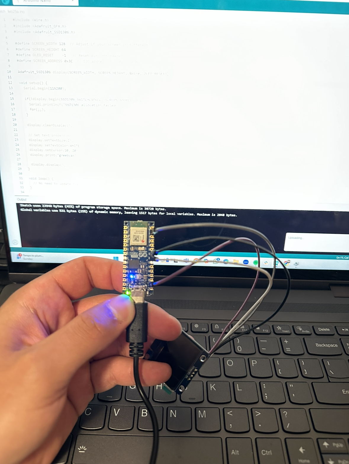

Test code was compiled to test the display functions, doesn't indicate any useful information yet such as battery life and incoming power. Circuits have been designed and idea of code is generated though, however parts haven't been ordered yet
Code compiled correctly, however it gets stuck uploading. We believe this is due to a data only USB wire being used, and shall be corrected.
Case Testing:
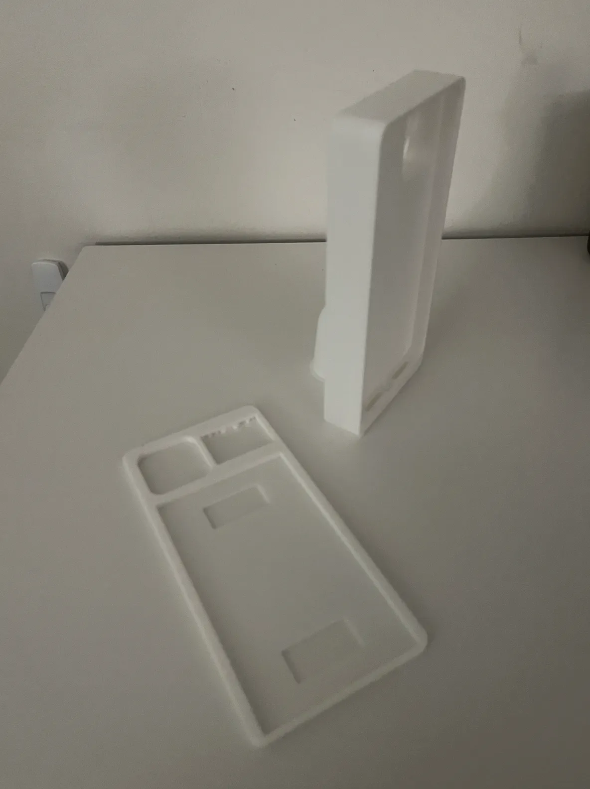
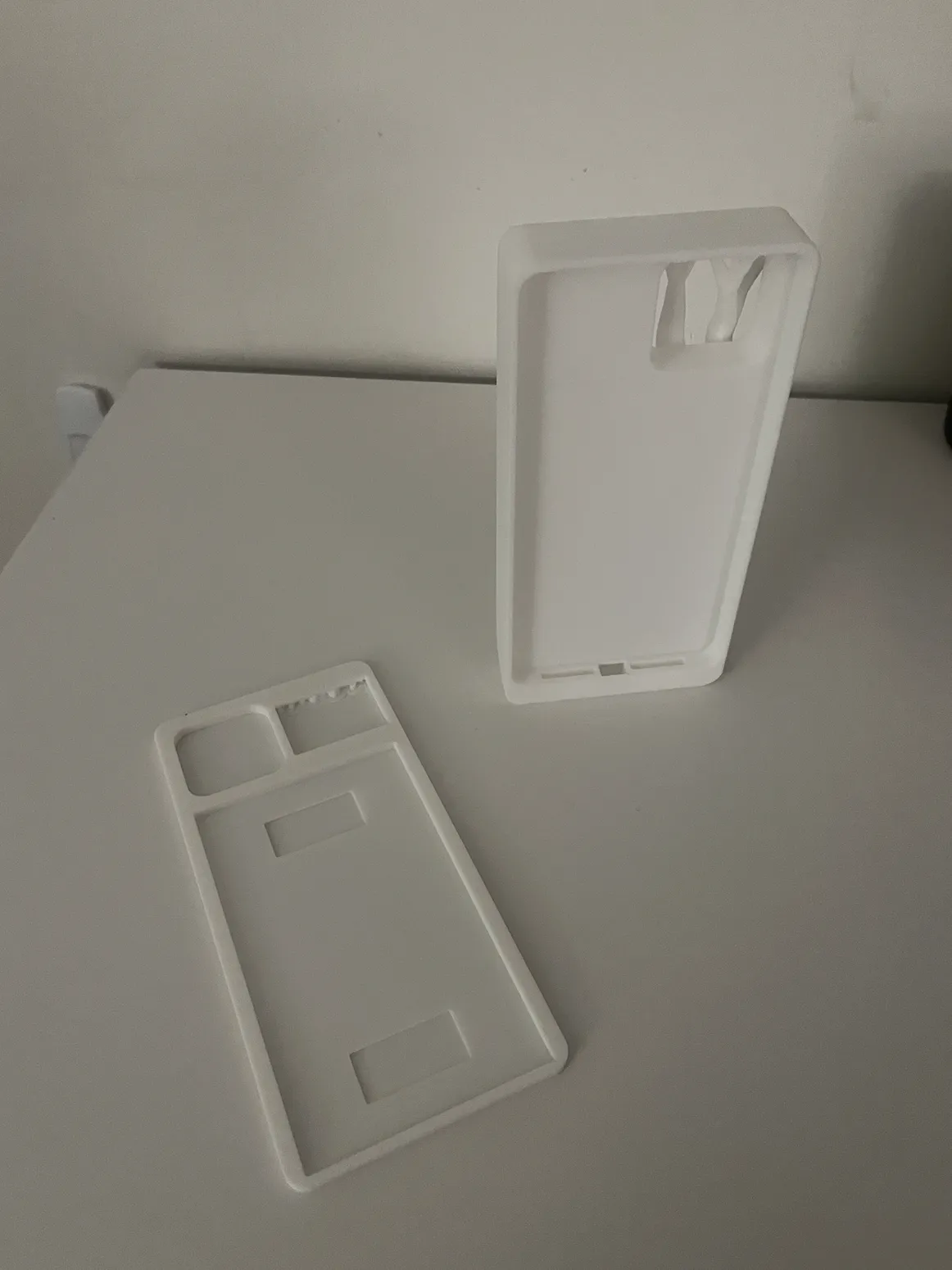
Case successfully 3D printed. The phone is a tight fit, however there are no cutouts or soft plastics for buttons such as the power button or volume control buttons.
Shall be fixed on next iterations using a soft plastic such as TPU or cutouts.
We also aim to add a lip to lip to the part that holds the phone to ensure it doesn't come loose on impact.
The housing just fits the electronics, however it is bulkier than we currently want it and the battery we shall use for the final iteration is larger than the testing battery. The charging wire used for testing also didn't pass through the designated hole to plug into the phone.
We plan to swap out some of the plug and play electronics and bulky wires with our own circuits and soldered wires to slim down the case and make more room for the larger battery.
The charging wire shall either be made thinner or replaced with a static part.
GREEN CASE